![Free eBooks of IT [BooksOfAll]](https://www.booksofall.com/wp-content/uploads/2022/06/booksofall-logo-2.png)
Mastering BPMN: Architecting the Bank Transfer System with Visual Paradigm
Welcome to this comprehensive tutorial on Business Process Modeling. In this guide, we will dissect a classic banking scenario: the management of financial accounts. We will explore how to translate business requirements into a technical Use Case Diagram using Visual Paradigm, the industry-standard tool for enterprise architecture and BPMN modeling.
This tutorial focuses on the system architecture of a banking application where a primary actor interacts with various financial services. By understanding the relationships between the actor and the system functions, you can design robust software requirements before writing a single line of code.
1. Understanding the Core Actors and Use Cases
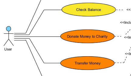
The foundation of any Use Case diagram is the Actor. An actor represents a role played by a user or an external system that interacts with the software. In our diagram, we see a stick figure labeled User.
- Actor (User): This is the primary initiator of the process. In a banking context, this could be an account holder, a teller, or an external API client.
Next, we have the Use Cases, represented by ovals. These describe specific functional goals the system must achieve for the actor. Our system architecture includes three critical financial functions:
- Check Balance (Yellow Oval): A read-only operation where the system retrieves the current account status.
- Donate Money to Charity (Orange Oval): A specific transaction type. The orange coloring often implies a specific category or priority in Visual Paradigm’s styling.
- Transfer Money (Orange Oval): The core transaction function, likely involving moving funds between two accounts.
2. Mapping Relationships and Associations
In Visual Paradigm, the lines connecting the User to the ovals are called Associations. These represent the communication paths. When you draw a line from the User to “Transfer Money,” you are defining the boundary of the system.
Key Modeling Concept: Every line indicates a valid interaction. If a line is missing, the User cannot perform that action. This helps in requirement analysis by ensuring no critical user goal is left unconnected.
3. Advanced Modeling: The <> Relationship
The diagram features dashed arrows labeled <<Include>>. This is a crucial concept in modeling complex workflows.
An Include relationship means that the base use case (the source of the arrow) requires the functionality of the included use case (the target) to complete its task. It is a mandatory dependency.
In our banking example, the logic flows like this:
- The User initiates Transfer Money.
- To complete a transfer, the system must verify the user’s identity or check the available balance.
- This dependency is modeled as an <
> relationship pointing to a (possibly implicit or external) sub-function.
Visual Paradigm handles these relationships by allowing you to define “Inclusion Points” in your model, ensuring that the Check Balance logic is reused across multiple transactions without duplicating the model.
4. Step-by-Step: Building this Diagram in Visual Paradigm
Let’s walk through how to recreate this architecture using the Visual Paradigm tool interface.
- Start a New Diagram: Navigate to
New Diagram > UML > Use Case Diagram. - Add the Actor: Select the Actor tool from the toolbar and click on the canvas. Rename the default instance to
User. - Create Use Cases: Select the Use Case tool (the oval) and create three instances.
- Name them:
Check Balance,Donate Money to Charity, andTransfer Money.
- Name them:
- Style the Diagram: Right-click on the ovals to select “Properties” or “Style.” Change the fill color of “Check Balance” to yellow and the transaction cases to orange to match our visual hierarchy.
- Connect the Actors: Use the Association tool to draw solid lines from the User to each Use Case.
- Define Inclusions: To add the <
> logic: - Select the Include relationship tool (usually a dashed line with a specific arrowhead).
- Draw from the “Transfer Money” use case to the required function (e.g., “Check Balance” or a “Authenticate User” use case).
- Label the relationship explicitly with
<<Include>>.
5. Why Visual Paradigm for System Architecture?
Visual Paradigm is not just a drawing tool; it is a comprehensive platform for the software lifecycle. When modeling diagrams like the one above, the tool offers:
- Automatic Synchronization: Changes made in the Use Case Diagram can be propagated to the Code Generator or the Activity Diagram.
- Standard Compliance: It strictly adheres to UML 2.x standards, ensuring that diagrams are readable by any other industry-standard tool.
- Enterprise Integration: As a cross-platform tool (Windows, Linux, Mac OS), it allows teams to collaborate seamlessly regardless of their operating system.
By mastering these basic modeling concepts—Actors, Use Cases, and Relationships—you lay the groundwork for complex BPMN analysis and software architecture design.