How the C4 Model Simplifies Complex System Design for New Architects
System architecture is one of the most critical responsibilities a software professional undertakes. As systems grow in size and complexity, the ability to communicate design decisions becomes just as important as the code itself. For new architects, the sheer volume of information can be overwhelming. How do you represent a microservices ecosystem without drowning in details? How do you explain database relationships to non-technical stakeholders? The C4 Model provides a structured approach to visualizing software architecture at multiple levels of abstraction. This guide explores how adopting this model can streamline your design process and improve team alignment.
🤔 The Challenge of System Complexity
Modern software systems rarely exist in isolation. They interact with external services, databases, user interfaces, and legacy infrastructure. When you attempt to draw a single diagram representing the entire system, you quickly encounter a problem: information overload. A diagram that shows every database table and every API endpoint becomes unreadable within minutes. Conversely, a diagram that only shows high-level boxes fails to provide actionable guidance for developers.
This tension between detail and abstraction is where the C4 Model excels. It does not force you to choose one representation for all audiences. Instead, it offers a hierarchy of diagrams tailored to specific questions and stakeholders. By separating concerns into distinct layers, you can maintain clarity regardless of the system size.
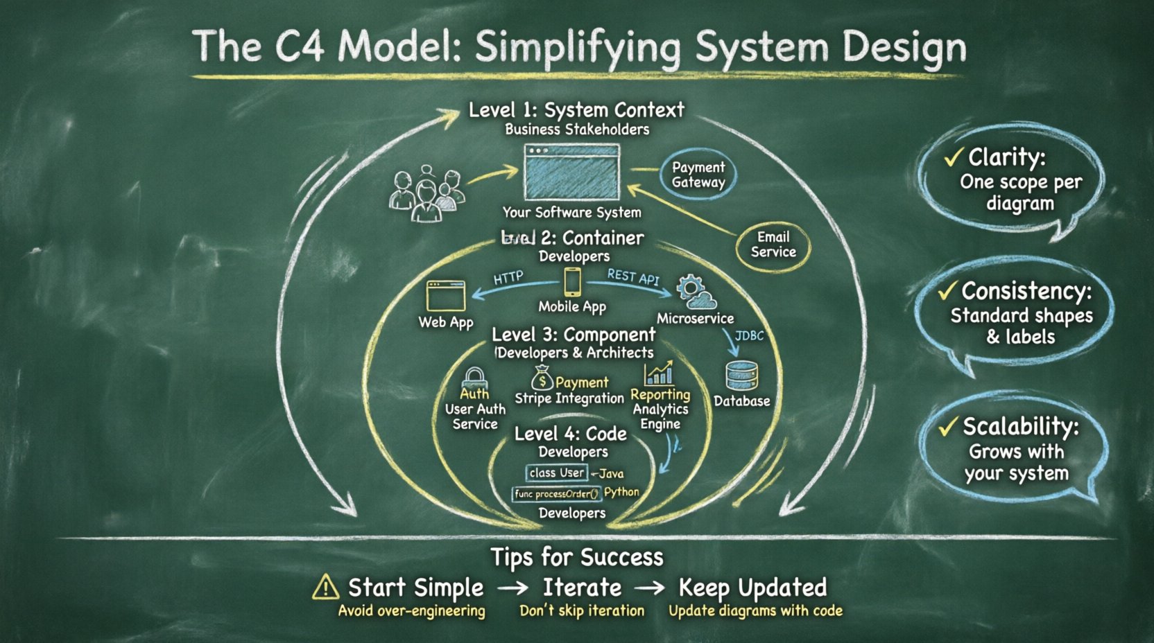
- Clarity: Each diagram focuses on a specific scope.
- Consistency: Standard shapes and labels reduce confusion.
- Scalability: The model grows with your system.
📐 What is the C4 Model?
The C4 Model is a collection of diagrams designed to document software architecture. It was created to solve the problem of inconsistent documentation across teams. The model is built on a simple principle: abstraction levels. Each level zooms in on the system to reveal more detail, much like a map that shows countries, then cities, then streets.
The hierarchy consists of four distinct levels. You do not need to create diagrams for every single level in every project. You select the levels that provide the most value for your current context. This flexibility is a key advantage for architects who need to balance documentation effort with business value.
📊 The Four Levels at a Glance
| Level | Name | Focus | Typical Audience |
|---|---|---|---|
| 1 | System Context | The whole system and its users | Business stakeholders, Project managers |
| 2 | Container | High-level runtime environments | Developers, System Architects |
| 3 | Component | Logical groups of functionality | Developers, Technical Leads |
| 4 | Code | Classes and functions | Developers (Code Review) |
🌍 Level 1: System Context
The first level is the broadest view. It answers the question: What is this system, and how does it fit into the larger world? This diagram is often the starting point for any architectural discussion. It defines the boundary of your system and identifies the actors who interact with it.
Key Elements
- Software System: Represented as a single box, usually in the center.
- People: Users or external actors who interact with the system.
- Other Systems: External APIs, databases, or services that integrate with your system.
- Relationships: Lines showing how data flows between the system and external entities.
This level is crucial for setting expectations. It prevents scope creep by clearly defining what is inside the boundary and what is outside. If a stakeholder asks about a feature that falls outside the context, you can refer to this diagram to clarify boundaries. It is also an excellent tool for onboarding new team members who need to understand the ecosystem quickly.
When creating a System Context diagram, focus on the who and the what. Avoid technical jargon. Use terms that business stakeholders understand. For example, instead of “REST API Endpoint,” use “Web Application.” This ensures that the diagram serves its purpose as a communication tool rather than a technical specification.
📦 Level 2: Container
Once the context is established, the next step is to look inside the box. Level 2 breaks down the software system into containers. A container is a runtime environment where the code executes. Common examples include web applications, mobile apps, microservices, and databases.
Defining Containers
A container is not a physical server. It is a logical unit. A single container might run on multiple servers, and multiple containers might share the same server. The diagram focuses on the technology stack and the communication protocols used between containers.
- Web Application: A browser-based interface.
- Mobile Application: A native or hybrid app for smartphones.
- Microservice: A standalone process serving a specific business capability.
- Database: A data store persisting information.
At this level, you document how containers communicate. Are they using HTTP, gRPC, or message queues? Are they connecting directly or through an API gateway? This information is vital for understanding system resilience and performance bottlenecks. It also helps developers understand the deployment topology without needing to read the infrastructure code.
Benefits of Container Diagrams
- Clarifies deployment boundaries.
- Identifies integration points early.
- Helps plan for scalability and security.
- Reduces ambiguity about technology choices.
⚙️ Level 3: Component
Zooming in further, Level 3 focuses on the components within a container. A component is a logical grouping of functionality. It represents a cohesive unit of work, such as a module, a package, or a subsystem. This level is where the logic of the application lives.
Component Characteristics
Components are not physical files. They are design abstractions. A single component might span multiple source files, and a single file might contain multiple components. The goal is to group code based on responsibility. If a component changes, it should usually change in isolation from other components.
- Responsibility: Each component has a specific job (e.g., “Payment Processing,” “User Authentication,” “Reporting Engine”).
- Interfaces: Components communicate via defined APIs or events.
- Dependencies: You can see which components rely on others.
This level is often the most detailed diagram architects create. It serves as a blueprint for developers. When a developer is assigned a task, this diagram tells them which component to modify and which existing components they must interact with. It promotes separation of concerns and makes refactoring easier because dependencies are explicit.
When to Stop at Level 3
For many projects, Level 3 is sufficient. It provides enough detail for development without getting bogged down in implementation specifics. If you find yourself needing to draw every class and method, you are likely over-documenting. The component level should capture the structure of the software, not the syntax.
💻 Level 4: Code
The final level dives into the code itself. This involves classes, functions, variables, and methods. While technically part of the C4 hierarchy, this level is rarely documented in formal architecture diagrams. It is typically covered by the code comments and the source code itself.
Role of Level 4 Diagrams
Diagramming code is expensive. The code changes frequently, making static diagrams obsolete quickly. Instead, use this level to document complex algorithms or critical data flows that are hard to understand from reading the code alone. Tools that generate diagrams from source code can be helpful here, but manual maintenance is usually not sustainable.
- Use Case: Documenting a complex encryption algorithm.
- Use Case: Explaining a specific data transformation pipeline.
- Use Case: Onboarding a new developer to a legacy codebase.
Most teams skip this level for general architecture documentation. It is better to keep the diagram focused on the higher-level structure and rely on code reviews for implementation details.
🚀 Benefits for New Architects
Adopting the C4 Model offers several advantages for those new to architecture. It provides a framework that removes the guesswork from documentation.
1. Reduced Cognitive Load
By breaking the system into levels, you do not have to hold the entire system in your mind at once. You can focus on the context, then the containers, then the components. This step-by-step approach prevents overwhelm.
2. Improved Communication
Stakeholders often have different information needs. Executives care about the business value (Level 1), while engineers care about the implementation (Level 3). The C4 Model allows you to tailor the diagram to the audience without losing the connection between them.
3. Documentation Consistency
When multiple architects work on the same project, consistency is key. The C4 Model defines standard shapes and labels. This means anyone can look at a diagram and understand it, regardless of who drew it.
4. Future-Proofing
As systems evolve, the diagrams evolve. Because the model is abstract, you can change the underlying technology without redrawing the entire diagram. If you switch from a monolithic application to microservices, you update the Container level, but the System Context remains the same.
⚠️ Common Pitfalls to Avoid
While the model is robust, it is easy to misuse it. New architects often fall into specific traps that reduce the value of the diagrams.
- Over-Engineering: Creating diagrams for every single component in a large system. Focus on the critical paths and complex areas.
- Ignoring Updates: A diagram is useless if it does not match the code. Integrate diagram updates into your deployment pipeline or sprint planning.
- Too Much Detail: Including database table structures in the Container level. Keep the focus on the runtime environment, not the schema.
- One Size Fits All: Trying to force every diagram into the same format. Adapt the detail level to the project size.
- Lack of Collaboration: Creating diagrams in isolation. Architecture is a team effort. Review diagrams with the development team to ensure accuracy.
🛠️ Implementation Strategy
How do you introduce this model to a team? Here is a practical approach to getting started without disrupting existing workflows.
Step 1: Start with Context
Begin by drawing the System Context diagram. This is the easiest level and provides immediate value. Get agreement on the boundaries and external dependencies before moving inward.
Step 2: Define Containers
Once the context is agreed upon, break down the system into containers. This is where you define the technology stack. Decide on the runtime environments and how they connect.
Step 3: Drill Down as Needed
Only create Component diagrams for containers that are complex. If a container is simple, the Container level might be sufficient. Avoid drawing components for trivial services.
Step 4: Integrate with Workflow
Make diagramming part of the definition of done. If a feature requires a new container or component, the diagram should be updated alongside the code. This ensures the documentation stays relevant.
🔄 Iterative Design
Architecture is not a one-time task. It is an iterative process. The C4 Model supports this by allowing you to refine diagrams as you learn more about the system. You might start with a rough System Context and refine it as you discover new external dependencies.
This iterative approach reduces the pressure to be perfect immediately. It is better to have a simple, accurate diagram than a complex, outdated one. Encourage your team to treat diagrams as living documents that evolve with the software.
📝 Summary
Effective system design requires clear communication. The C4 Model provides a proven structure to manage complexity without sacrificing detail. By using levels of abstraction, you can cater to different audiences while maintaining a single source of truth. For new architects, this model offers a scaffold to build upon, reducing the risk of confusion and misalignment. Focus on the core levels, keep diagrams updated, and prioritize clarity over completeness. With this approach, you can navigate complex systems with confidence and precision.


Comments (0)