C4 Model for Cross-Team Collaboration: Bridging Gaps in Distributed Teams
In the modern landscape of software development, distributed teams are the norm rather than the exception. Engineers working across time zones, organizations, and geographies face unique challenges when it comes to understanding the big picture. A common pain point is the fragmentation of knowledge. One team owns the database, another handles the API gateway, and a third manages the user interface. Without a shared language, communication breaks down, leading to integration errors, duplicated effort, and slow delivery.
This is where a standardized approach to software architecture documentation becomes critical. The C4 Model offers a practical framework for visualizing and communicating system design. By providing a clear hierarchy of abstraction, it allows different stakeholders to engage with the architecture at the level of detail that matters to them. This guide explores how adopting the C4 Model can bridge communication gaps in distributed teams, streamline collaboration, and reduce technical debt.
🤔 The Challenge of Distributed Collaboration
When teams are co-located, informal communication often fills the gaps in documentation. A quick walk to a colleague’s desk can resolve ambiguities. In a distributed environment, that spontaneity is lost. Relying solely on code comments or dense technical specifications often fails to convey the intent behind system boundaries. Misunderstandings arise when:
- Context is missing: New team members struggle to understand how their service fits into the larger ecosystem.
- Boundaries are unclear: It is unclear which team owns which responsibility, leading to overlapping work.
- Language varies: Product managers speak business value, while engineers speak implementation details. They need a bridge.
Visual models act as that bridge. However, not all diagrams serve the same purpose. A complex class diagram might satisfy a senior architect but confuse a product owner. The C4 Model addresses this by offering a tiered approach to visualization, ensuring the right level of detail reaches the right audience.
📐 What is the C4 Model?
The C4 Model is a conceptual framework for describing software architecture. It breaks down a system into four distinct levels of abstraction. This hierarchy prevents information overload and focuses communication on relevant details. Instead of trying to show everything at once, the model encourages starting high and drilling down only when necessary.
Each level serves a specific purpose and targets a specific audience within an organization. By adhering to this structure, teams can maintain a single source of truth that remains relevant over time.
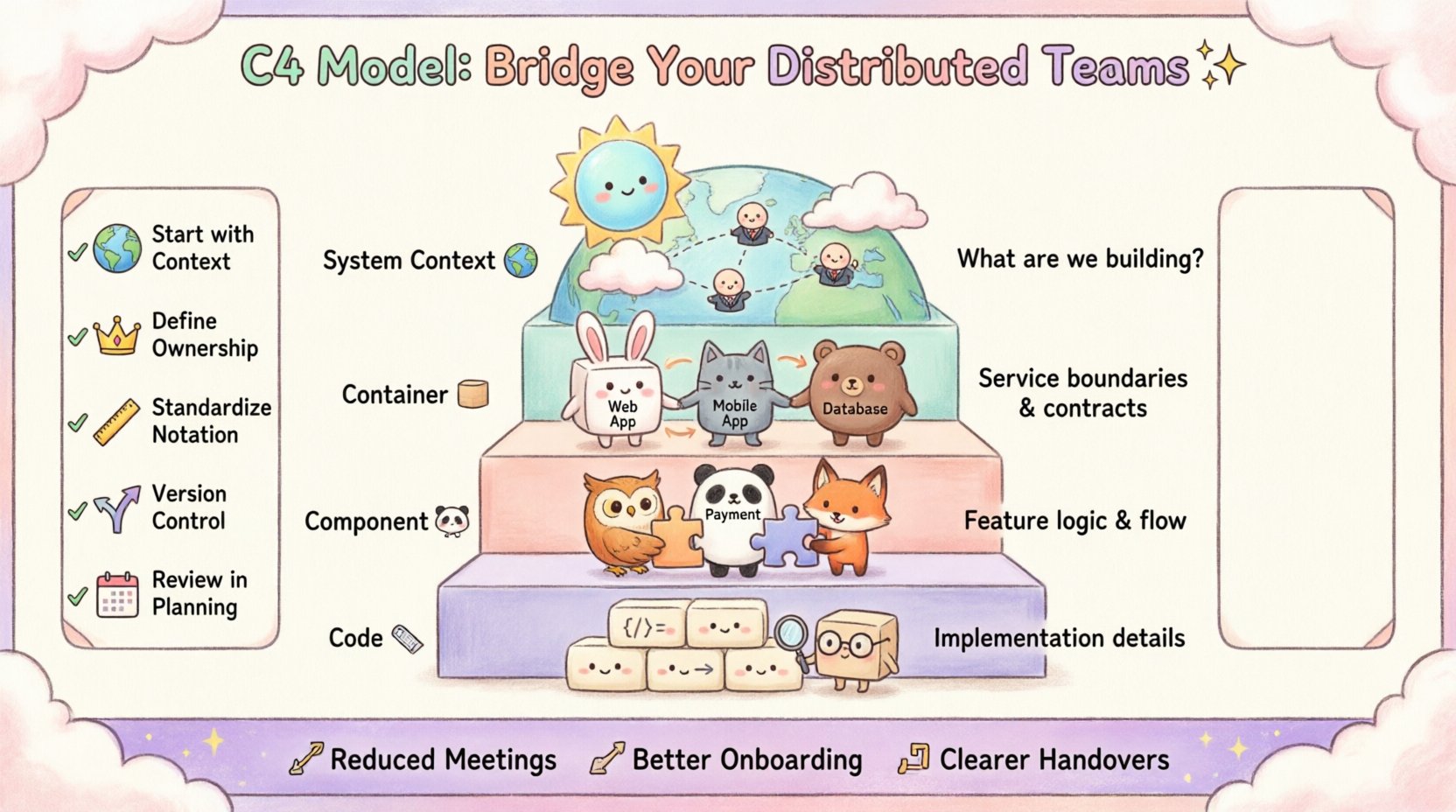
1. System Context Diagram 🌍
The top level focuses on the system as a whole. It shows the system itself and the people or systems that interact with it. This diagram is crucial for aligning stakeholders who are not deeply technical.
- Scope: The entire application or product.
- Audience: Business stakeholders, project managers, and new developers.
- Key Elements: The system, users, and external dependencies.
In a distributed setting, this diagram answers the question: “What are we building and who is it for?” It prevents scope creep by clearly defining the boundary of the system.
2. Container Diagram 📦
Once the system boundary is defined, the next level breaks it down into high-level building blocks. These are called containers. A container is a distinct unit of deployment, such as a web application, a mobile app, or a database.
- Scope: Major architectural components within the system.
- Audience: Architects, team leads, and senior developers.
- Key Elements: Containers and the data flow between them.
This level is vital for cross-team alignment. If Team A owns the Web Application container and Team B owns the Database container, this diagram clarifies the contract between them. It defines the interfaces without getting bogged down in code details.
3. Component Diagram 🧩
Within a single container, the architecture is further divided into components. These represent groups of functionality, such as a payment processing module or a user authentication service.
- Scope: Internal structure of a container.
- Audience: Developers working on specific features.
- Key Elements: Components and their interactions.
For feature teams, this diagram is the blueprint. It shows how different pieces of logic interact within the service. It helps identify coupling and potential performance bottlenecks before code is written.
4. Code Diagram 📝
The lowest level details the structure of the code itself, mapping to classes and interfaces. While useful for specific debugging or deep refactoring, this level is rarely needed for high-level collaboration.
- Scope: Individual classes and methods.
- Audience: Developers implementing specific features.
- Key Elements: Classes, interfaces, and relationships.
Many organizations choose to stop at the Component level. Code changes too frequently to maintain accurate diagrams at this level without significant overhead.
🤝 Mapping C4 Levels to Team Structures
To maximize the benefit of the C4 Model in a distributed environment, teams must understand which level corresponds to their workflow. Here is how different roles can leverage each tier.
| C4 Level | Primary Audience | Team Focus | Communication Goal |
|---|---|---|---|
| System Context | Stakeholders, PMs | Product Vision | Define scope and external dependencies |
| Container | Architects, Leads | Service Ownership | Define boundaries and contracts |
| Component | Developers | Feature Implementation | Define logic and internal flow |
| Code | Developers | Refactoring & Debugging | Understand specific implementation details |
Aligning Service Teams
In microservices architectures, the Container level is often the sweet spot for collaboration. Each microservice is a container. When Team A needs to integrate with Team B’s service, the Container diagram defines the API contract. It prevents Team A from assuming how Team B’s internal logic works, adhering to the principle of loose coupling.
Aligning Feature Teams
When a team owns a specific feature set that spans multiple containers, the Component diagram becomes essential. It allows the team to visualize how their feature interacts with shared resources. This visibility helps in identifying potential conflicts during code reviews or sprint planning.
🚀 Implementing C4 for Collaboration
Adopting a new modeling standard requires a shift in culture, not just a change in tools. Here is a practical approach to introducing the C4 Model to your distributed teams.
- Start with Context: Ensure every new project begins with a System Context diagram. This sets the stage for everyone.
- Define Ownership: Use the Container diagram to assign ownership. Clearly state which team is responsible for which container.
- Standardize Notation: Agree on a set of symbols. For example, always use a specific icon for databases or human users. Consistency reduces cognitive load.
- Store in Version Control: Keep diagrams alongside the code. This ensures they evolve with the product and are accessible to remote workers.
- Review in Planning: Include diagram updates in the sprint planning process. If the architecture changes, the diagram must change.
🛠️ Avoiding Common Pitfalls
Even with a solid framework, teams often stumble during implementation. Being aware of these common issues can save time and prevent frustration.
1. Over-Modeling
Creating diagrams for every minor detail leads to maintenance fatigue. If a diagram is too complex, people will stop updating it. Aim for clarity over completeness. If a diagram does not aid decision-making, it is likely too detailed.
2. Ignoring the “Why”
Diagrams should explain decisions, not just structure. A static picture of the architecture is less valuable when paired with an Architecture Decision Record (ADR). The ADR explains the reasoning behind a specific choice, while the C4 diagram shows the result.
3. Inconsistent Naming
If one team calls a service “User Service” and another calls it “Identity Provider,” confusion arises. Establish a naming convention early. Use business-oriented names where possible to ensure non-technical stakeholders understand the model.
4. Treating it as a One-Time Task
Documentation is not a one-off activity. As features are added and technologies evolve, the system changes. Treat diagrams as living documents. Assign ownership for maintaining the documentation just as you would for the code.
📊 The Role of Architecture Decision Records
While the C4 Model visualizes the “what,” Architecture Decision Records (ADRs) document the “why.” Combining these two tools creates a robust documentation strategy.
- ADRs capture context: Why was a specific database chosen? Why was a certain protocol selected?
- C4 captures state: What does the system look like today?
- Together they guide evolution: When a new feature is proposed, teams can check the ADRs to see if they align with past decisions and check the diagrams to see if they fit the current architecture.
This combination is particularly powerful for remote teams. A new hire can read the ADRs to understand the history and look at the diagrams to understand the current state, reducing the time needed for onboarding.
🔄 Maintenance and Evolution
Documentation rot is a real threat. Diagrams become outdated quickly if not managed. To prevent this, integrate diagram updates into the development workflow.
Automated Generation
Some tools can generate diagrams directly from code or configuration files. This reduces the manual effort required to keep documentation current. However, ensure the generated output is readable and follows the C4 standards.
Code Review Integration
Include documentation updates in pull requests. If a developer changes the API structure, they should also update the Container diagram. This makes documentation part of the quality assurance process.
Scheduled Reviews
Hold quarterly reviews of the architecture diagrams. Ask the team: “Does this still reflect reality?” If significant changes have occurred without updates, schedule a session to refresh the models.
🌐 Benefits for Distributed Workflows
The advantages of using the C4 Model extend beyond simple documentation. It fundamentally changes how distributed teams interact.
Reduced Meeting Load
When a diagram clearly shows the data flow, fewer meetings are needed to explain how systems connect. Teams can reference the visual artifact during calls instead of verbally walking through complex logic.
Better Onboarding
New engineers often feel lost in large codebases. A set of C4 diagrams provides a map. They can start with the Context diagram to see where they fit, then drill down to the Container or Component level to understand their specific responsibilities.
Clearer Handovers
When teams rotate or restructure, the diagrams serve as a neutral reference point. They remove ambiguity about ownership. If a service boundary is unclear, the diagram provides the answer.
🧩 Integrating with Agile Practices
Agile methodologies emphasize iterative delivery and adaptability. The C4 Model fits well within this philosophy because it allows for incremental detail.
- Sprint Planning: Teams can sketch a Component diagram to plan the work for the upcoming sprint.
- Refinement: During backlog refinement, the Container diagram helps identify dependencies between teams.
- Retrospectives: Review the diagrams to see if the architecture supported the delivery. If not, identify what needs to change.
This integration ensures that architecture is not a separate phase but a continuous activity woven into the development cycle.
🔍 Case Study: Aligning Frontend and Backend
Consider a scenario where a Frontend Team and a Backend Team are working in different time zones. The Backend Team updates the API, but the Frontend Team is unaware of the changes until deployment.
Without C4: The Frontend Team relies on a shared document that is rarely updated. They discover the breaking change during testing.
With C4: The Backend Team updates the Container diagram to reflect the new API endpoint. They tag the Frontend Team in the repository notification. The diagram serves as the contract. The Frontend Team sees the change immediately and updates their client code accordingly.
This scenario highlights how visual clarity prevents integration failures. It turns a potential conflict into a coordinated update.
📝 Conclusion
Collaboration in distributed teams requires intentional design. The C4 Model provides a structured way to visualize and communicate software architecture. By separating concerns into Context, Containers, Components, and Code, it ensures that every stakeholder receives information appropriate to their role.
Adopting this model is not about creating perfect drawings. It is about creating a shared understanding. It reduces the friction of cross-team communication, speeds up onboarding, and aligns technical work with business goals. When teams invest in clear, maintained, and standardized architecture documentation, they build a foundation for sustainable growth.
Start small. Draw one Context diagram. Share it with your team. Get feedback. Then move to Containers. With consistency and discipline, the C4 Model becomes more than a documentation standard—it becomes a communication tool that keeps your distributed team in sync.


Comments (0)