C4 Model in Practice: Real-World Examples from Enterprise Environments
In modern enterprise settings, software architecture is rarely a single, monolithic entity. It is a complex ecosystem of services, databases, and integrations spread across multiple teams and technologies. Visualizing this complexity is a significant challenge. When documentation is vague or outdated, communication breaks down, and technical debt accumulates. The C4 model provides a structured approach to creating software architecture diagrams that scale from high-level context down to the code level. This guide explores how to apply the C4 model effectively in large-scale enterprise environments, offering practical examples and strategies for implementation.
📚 Understanding the C4 Model Levels
The C4 model organizes architecture documentation into four distinct levels. Each level serves a specific audience and purpose. Understanding the distinction between these levels is crucial for maintaining clarity.
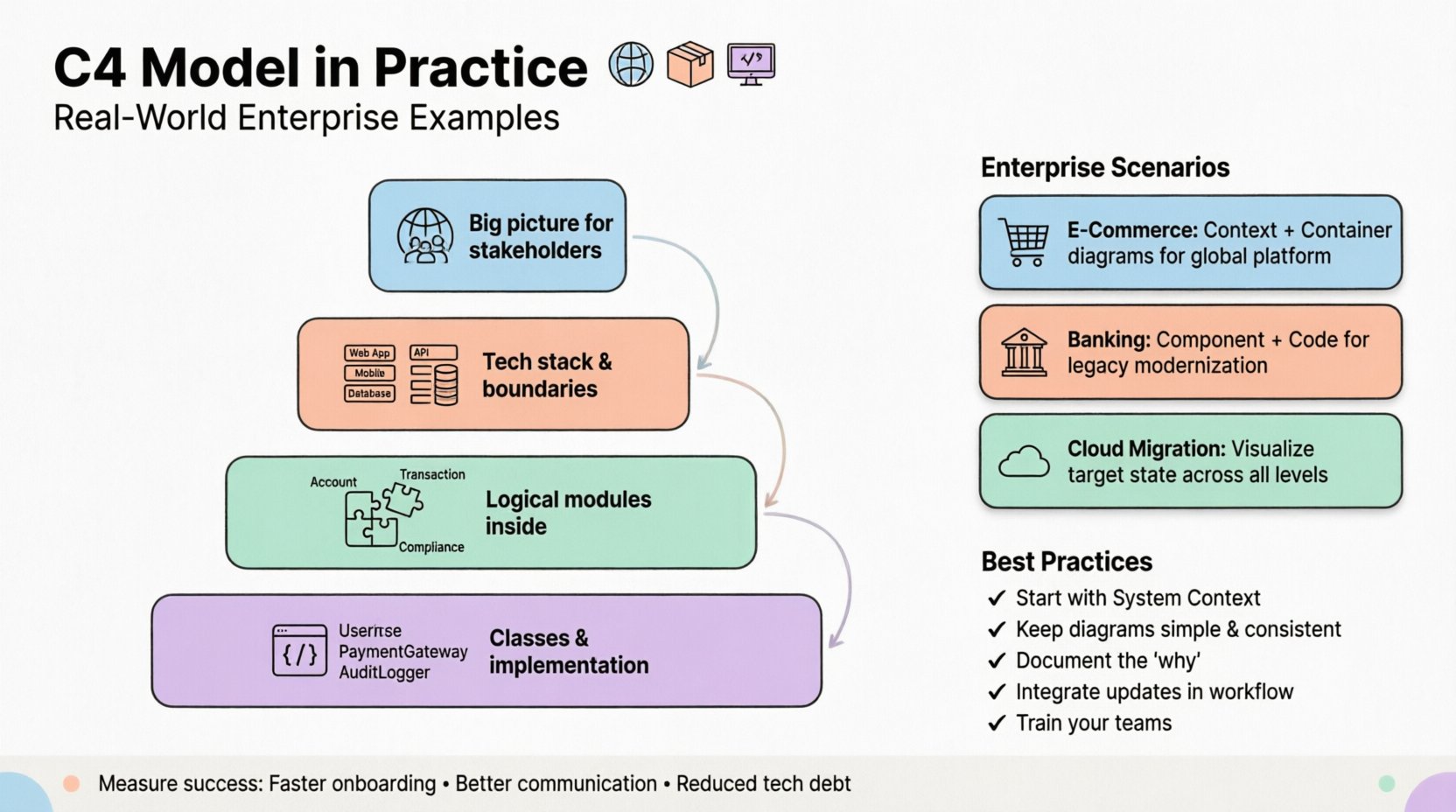
- Level 1: System Context 🌍 This diagram shows the software system as a single box and depicts the people and other systems that interact with it. It provides the “big picture” view for stakeholders.
- Level 2: Container Diagrams 📦 This level breaks down the system into high-level building blocks, such as web applications, mobile apps, and databases. It focuses on technology choices and boundaries.
- Level 3: Component Diagrams 🧩 Inside each container, this diagram shows the major logical components. It describes the internal structure without getting into implementation details.
- Level 4: Code Diagrams 💻 This level maps components to code structures, such as classes and packages. It is typically generated automatically or used for specific team-level design reviews.
🏭 Enterprise Scenario 1: Global E-Commerce Platform
Consider a large retail organization managing online sales across multiple regions. Their architecture involves a web portal, a mobile application, and a backend processing system. The team consists of hundreds of engineers split across different squads.
🌍 System Context Diagram
The context diagram here is essential for new hires and executives. It defines the boundaries of the e-commerce platform.
- System: The primary E-Commerce Platform.
- External Actors: Customers, Administrators, Payment Processors, Inventory Management Systems.
- Relationships: Customers browse and purchase. Payment Processors handle transactions. Inventory Systems update stock levels.
This high-level view prevents scope creep. It clarifies that the team owns the platform but relies on third-party services for payments. It establishes trust boundaries and data flow directions at a glance.
📦 Container Diagram
Once the context is set, the architecture team needs to understand how the system is built. The container diagram reveals the technology stack.
- Frontend Web App: Built with a modern framework, hosted on a content delivery network.
- Mobile App: Native iOS and Android applications communicating via APIs.
- API Gateway: Handles routing, authentication, and rate limiting.
- Database Cluster: Relational database for transactional data, NoSQL for catalog data.
- Search Engine: Dedicated service for product search functionality.
The arrows between containers show data flow. For example, the Mobile App sends requests to the API Gateway, which then routes them to the appropriate service. This level helps infrastructure teams plan load balancing and security policies.
🏦 Enterprise Scenario 2: Banking System Modernization
Financial institutions often face the challenge of migrating legacy systems to modern architectures while maintaining strict regulatory compliance. The C4 model helps document the transition path.
🧩 Component Diagrams
In a banking scenario, the component diagram is vital for understanding the logic within a specific container, such as the Core Banking Service.
- Account Management Component: Handles creation and updates of customer accounts.
- Transaction Processing Component: Validates and records money movements.
- Notification Component: Sends alerts to customers regarding account activity.
- Compliance Check Component: Ensures all actions meet regulatory requirements.
This level allows architects to see dependencies between logical modules. If the Compliance Check Component is updated, the team knows immediately which other components might be affected. It aids in impact analysis without needing to read the source code.
💻 Code Diagrams
For the Core Banking Service, code diagrams map the components to actual classes. This is useful during code reviews or when debugging complex issues.
- Classes:
AccountService,TransactionValidator,ComplianceRuleEngine. - Interfaces: Defines contracts between the components.
- Dependencies: Shows how classes interact within the container.
This level is often automated. Tools can extract this information from the source code repository to ensure the documentation matches the actual implementation. This reduces the maintenance burden significantly.
☁️ Enterprise Scenario 3: Cloud Migration Strategy
Many enterprises are moving from on-premise data centers to public cloud providers. The C4 model assists in planning this migration by visualizing the target state.
| Diagram Level | Focus | Target Audience |
|---|---|---|
| System Context | External dependencies | Stakeholders, Management |
| Container | Technology selection | Architects, DevOps |
| Component | Logical structure | Developers, Team Leads |
| Code | Implementation details | Developers |
🔄 Migration Path
During migration, the diagrams evolve. The initial state might show a monolithic application hosted on-premise. The target state shows a containerized microservices architecture.
- Phase 1: Lift and shift. The container diagram shows the same application moving to the cloud infrastructure.
- Phase 2: Decomposition. The monolith is split into smaller services. New container boxes are added to the diagram.
- Phase 3: Optimization. The component diagram is refined to reflect new internal structures.
Visualizing these phases helps project managers track progress. It ensures that the migration does not break existing integrations defined in the context diagram.
🛠️ Implementation and Maintenance
Creating the diagrams is only the first step. Maintaining them requires a strategy.
📝 Living Documentation
Documentation that is not updated becomes a liability. The C4 model works best when treated as a living artifact.
- Version Control: Store diagram definitions in the same repository as the code.
- Automated Generation: Use tools to generate code-level diagrams from the source.
- Review Process: Include diagram updates in the definition of done for pull requests.
👥 Roles and Responsibilities
Who is responsible for what?
- System Architects: Define the System Context and high-level Container diagrams.
- Lead Developers: Refine Component diagrams for their specific domains.
- Engineering Teams: Maintain Code diagrams or ensure they stay in sync.
This distribution of responsibility ensures that no single person is overwhelmed by the documentation effort.
⚠️ Common Pitfalls to Avoid
Even with a solid model, teams often stumble. Here are common issues encountered in enterprise settings.
- Over-Engineering: Creating diagrams for every single minor feature. Focus on significant architectural changes.
- Tool Dependency: Relying on a specific tool that might become obsolete. Use standard formats like PlantUML or Mermaid when possible.
- Ignoring Audience: Showing code-level diagrams to executives. Match the diagram level to the reader’s needs.
- Static Snapshots: Updating diagrams only once a year. They should reflect the current state of the system.
🔍 Comparison with Traditional UML
While the Unified Modeling Language (UML) is well-established, it often lacks the abstraction needed for high-level architectural discussions.
- Clarity: C4 diagrams are simpler and easier to read for non-technical stakeholders.
- Flexibility: C4 allows for a mix of diagram styles without strict adherence to a single standard.
- Focus: C4 focuses on system structure rather than behavior, which fits modern microservice architectures better.
📈 Measuring Success
How do you know the C4 model is working for your organization?
- Onboarding Time: New engineers understand the system faster.
- Communication: Fewer misunderstandings during sprint planning.
- Documentation Quality: Less technical debt related to outdated docs.
- Decision Making: Architecture decisions are documented and traceable.
These metrics help justify the investment in maintaining the diagrams.
🚀 Future-Proofing Your Architecture
Technology trends change rapidly. The C4 model remains relevant because it focuses on concepts rather than specific implementations.
- Cloud Native: Containers and services fit the model naturally.
- Serverless: Functions can be treated as components or containers depending on granularity.
- Edge Computing: Context diagrams can easily show edge nodes interacting with central systems.
By keeping the model conceptual, you avoid the need to completely redraw your architecture every time a technology stack changes.
📌 Summary of Best Practices
- Start with the System Context before diving into details.
- Keep diagrams simple; avoid cluttering with too many boxes.
- Use consistent notation for boxes and arrows.
- Document the “why” behind architectural decisions.
- Integrate diagram updates into the development workflow.
- Train teams on how to read and create C4 diagrams.
Adopting the C4 model requires discipline, but the benefits for enterprise software engineering are substantial. It bridges the gap between abstract strategy and concrete implementation, ensuring that everyone involved in the project shares a common understanding of the system’s structure.


Comments (0)