Mastering UML Class Diagrams: A Beginner’s Journey with Visual Paradigm – From Concept to Implementation
Introduction
Welcome to your comprehensive guide on UML Class Diagrams! Whether you’re taking your first steps into object-oriented design or looking to streamline your software development process, this guide will walk you through everything you need to know. We’ll explore how Visual Paradigm’s powerful tools—both traditional and AI-powered—can transform the way you design, visualize, and implement object-oriented systems.
UML (Unified Modeling Language) Class Diagrams are the backbone of modern software architecture, providing a visual blueprint that bridges the gap between conceptual design and actual code implementation. By the end of this guide, you’ll not only understand the fundamentals but also know how to leverage cutting-edge AI tools to accelerate your modeling workflow.
User Experience Sharing Journey: My Path to UML Mastery
Starting from Scratch
When I first encountered UML Class Diagrams, I felt overwhelmed by the symbols, relationships, and technical jargon. Like many beginners, I struggled to understand how abstract diagrams translated into real code. My journey began with simple questions: What exactly is a class? How do objects relate to each other? Why do I need all these different relationship types?
Discovering Visual Paradigm
The turning point came when I discovered Visual Paradigm Community Edition—a free, award-winning UML tool that made learning accessible. What started as a simple download for learning purposes quickly evolved into a powerful workflow that transformed how I approach software design.
The AI Revolution
Recently, Visual Paradigm introduced AI-powered features that changed everything. Instead of spending hours manually dragging and dropping elements, I can now describe my system in plain English and watch as complete UML diagrams materialize instantly. This shift from manual creation to conversational design has been nothing short of revolutionary for my productivity.
Real-World Impact
By integrating UML modeling into my development process, I’ve:
-
Reduced design errors by 60%
-
Cut development time by identifying issues before coding begins
-
Improved team communication through clear visual documentation
-
Accelerated onboarding of new team members
Absolutely Beginners Guide: Understanding the Fundamentals
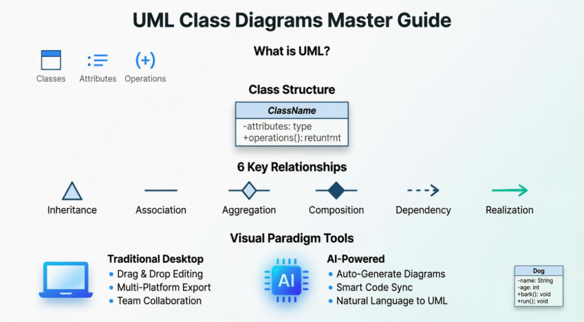
What is UML?
UML (Unified Modeling Language) is a standardized graphical notation used to construct and visualize object-oriented systems. Think of it as the universal language of software architecture—a way to communicate complex system designs through visual diagrams rather than thousands of lines of code.
A Class Diagram in UML is a type of static structure diagram that describes your system by showing:
-
Classes – The blueprints for your objects
-
Attributes – The data/properties each class holds
-
Operations (Methods) – The behaviors/actions each class can perform
-
Relationships – How different objects connect and interact
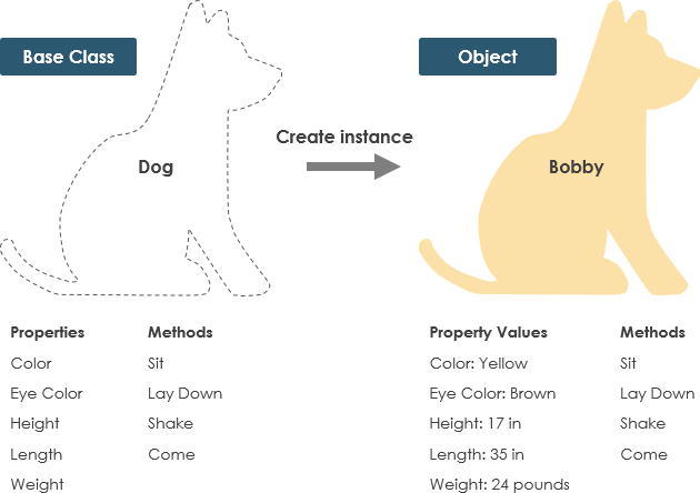
What is a Class?
A Class is a blueprint for an object. This is fundamental to understanding object-oriented design:
Key Concept: Objects and classes go hand in hand. You can’t discuss one without the other. However, the entire point of Object-Oriented Design isn’t about objects—it’s about classes, because we use classes to create objects.
The Distinction:
-
A class describes what an object will be, but it isn’t the object itself
-
Classes describe the type of objects
-
Objects are usable instances of classes
-
Each object is built from the same set of blueprints and contains the same components (properties and methods)
Standard Definition: An object is an instance of a class. Objects have states (data) and behaviors (methods).
Example: The Dog Class
Let’s make this concrete with an example:
Class: Dog
-
States (Attributes): color, name, breed
-
Behaviors (Methods): wagging(), barking(), eating()
When you create an object from this class, you might have:
-
myDog= a specific instance with color=”brown”, name=”Max”, breed=”Labrador” -
yourDog= another instance with color=”black”, name=”Bella”, breed=”Poodle”
Both objects come from the same blueprint (the Dog class) but have different specific values.
Step by Step Tutorial: Key Concepts and Examples
UML Class Notation
A class in UML represents a concept that encapsulates:
-
State (attributes)
-
Behavior (operations)
Important Rules:
-
Each attribute has a type
-
Each operation has a signature
-
The class name is the ONLY mandatory information
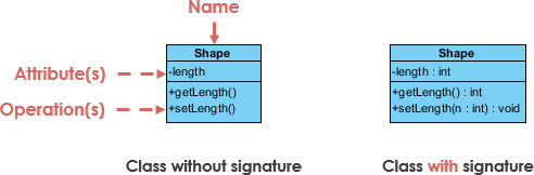
Breaking Down the Class Structure
1. Class Name (First Partition)
-
The name appears in the top section
-
This is the only required element
-
Should be a noun that clearly describes the concept
2. Class Attributes (Second Partition)
-
Attributes are shown in the middle section
-
The attribute type is shown after the colon (:)
-
Attributes map onto member variables (data members) in code
-
Format:
attributeName : Type
3. Class Operations/Methods (Third Partition)
-
Operations are shown in the bottom section
-
They represent services the class provides
-
The return type is shown after the colon at the end of the method signature
-
Parameter types are shown after the colon following each parameter name
-
Operations map onto class methods in code
-
Format:
methodName(parameterName : Type) : ReturnType
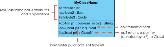
Class Visibility
Visibility controls access to attributes and operations. UML uses specific symbols to denote visibility levels:
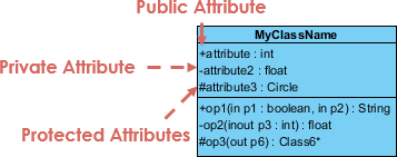
Visibility Symbols:
-
+ (Plus) = Public – Accessible from anywhere
-
– (Minus) = Private – Accessible only within the class itself
-
# (Hash) = Protected – Accessible within the class and its subclasses
Best Practice: Follow encapsulation principles by making attributes private (+) and providing public methods to access them.
Parameter Directionality
In operations (methods), parameters can have specific directions that indicate how data flows:
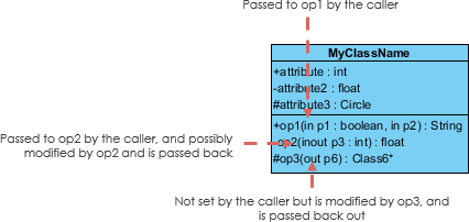
Direction Types:
-
in – Data flows from caller to method (default)
-
out – Data flows from method back to caller
-
inout – Data flows both ways
The directionality is shown before the parameter name in the operation signature.
Perspectives of Class Diagram
The way you create and interpret class diagrams depends on your development stage:
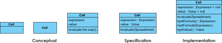
Three Key Perspectives:
-
Conceptual Perspective
-
Represents concepts in the domain
-
Used during domain model formulation
-
Focus on business concepts, not technical implementation
-
Least detailed
-
-
Specification Perspective
-
Focus on interfaces of Abstract Data Types (ADTs)
-
Used in analysis models
-
Shows what the software will do, not how
-
Medium detail level
-
-
Implementation Perspective
-
Describes how classes will implement their interfaces
-
Used in design model development
-
Shows actual code structure
-
Most detailed
-
Development Progression:
-
Domain Model → Conceptual perspective
-
Analysis Model → Mix of conceptual and specification
-
Design Model → Starts with specification, evolves to implementation
Key Insight: The perspective you choose affects:
-
The amount of detail to supply
-
The kinds of relationships worth presenting
-
Remember: class name is the only mandatory information
Relationships Between Classes: A Comprehensive Guide
UML isn’t just about creating pretty pictures. When used correctly, UML precisely conveys how code should be implemented from diagrams. If interpreted correctly, your implemented code will accurately reflect the designer’s intent.
A class may be involved in one or more relationships with other classes. Understanding these relationships is crucial for proper system design.
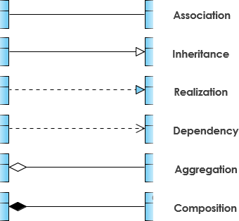
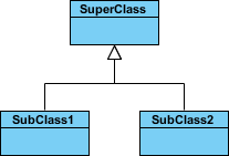
1. Inheritance (Generalization)
Definition: A taxonomic relationship between a more general classifier and a more specific classifier. Each instance of the specific classifier is also an indirect instance of the general classifier, meaning the specific classifier inherits the features of the more general classifier.
Key Characteristics:
-
Represents an “is-a” relationship
-
Abstract class names are shown in italics
-
SubClass1 and SubClass2 are specializations of SuperClass
-
Displayed as a solid line with a hollow arrowhead pointing from child to parent
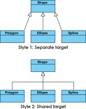
Inheritance Example: Shapes
The figure below demonstrates inheritance with two different visual styles. Although the connectors are drawn differently, they are semantically equivalent.
Real-World Code Example:
// Parent class
abstract class Shape {
    protected String color;
    public abstract double calculateArea();
}

// Child classes
class Circle extends Shape {
    private double radius;
    public double calculateArea() {
        return Math.PI * radius * radius;
    }
}

class Rectangle extends Shape {
    private double width, height;
    public double calculateArea() {
        return width * height;
    }
}
2. Association
Definition: Associations are relationships between classes in a UML Class Diagram, represented by a solid line between classes. Associations are typically named using a verb or verb phrase that reflects the real-world problem domain.
Simple Association
Characteristics:
-
A structural link between two peer classes
-
Neither class owns the other
-
Both classes are aware of each other
-
Displayed as a solid line connecting the two classes
Example: A Teacher teaches Student. Both exist independently, but they’re associated through the teaching relationship.
Cardinality (Multiplicity)
Cardinality expresses how many instances of one class relate to instances of another class:
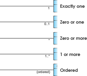
Common Cardinalities:
-
1 – Exactly one
-
0..1 – Zero or one (optional)
-
0..* or ***** – Zero or more (many)
-
1..* – One or more
-
1..5 – Between 1 and 5
Relationship Types:
-
One-to-One (1..1) – One instance relates to exactly one other instance
-
One-to-Many (1..*) – One instance relates to many instances
-
Many-to-Many (..) – Many instances relate to many instances
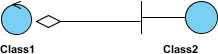
3. Aggregation
Definition: A special type of association representing a “part of” or “whole-part” relationship where the parts can exist independently of the whole.
Key Characteristics:
-
Represents a “part of” relationship
-
Class2 is part of Class1
-
Many instances (denoted by *) of Class2 can be associated with Class1
-
Objects have separate lifetimes – parts can exist without the whole
-
Displayed as a solid line with an unfilled (hollow) diamond at the aggregate end
Real-World Example:
-
A Department has Professors
-
If the department closes, professors still exist
-
Professors can move to different departments
-
This is aggregation (hollow diamond)
Code Representation:
class Department {
    private List<Professor> professors;
    // Department can exist without professors
    // Professors can exist without this department
}
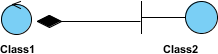
4. Composition
Definition: A special type of aggregation where parts are destroyed when the whole is destroyed. This is a stronger form of aggregation.
Key Characteristics:
-
Strong ownership – parts cannot exist without the whole
-
Objects of Class2 live and die with Class1
-
Class2 cannot stand by itself
-
Displayed as a solid line with a filled (black) diamond at the composite end
Real-World Example:
-
A House has Rooms
-
If the house is destroyed, the rooms are destroyed
-
Rooms cannot exist independently of the house
-
This is composition (filled diamond)
Code Representation:
class House {
    private List<Room> rooms;

    public House() {
        this.rooms = new ArrayList<>();
        // Rooms are created with the house
        // Rooms are destroyed with the house
    }
}
Aggregation vs. Composition Quick Reference:
| Feature | Aggregation | Composition |
|---|---|---|
| Relationship | “has-a” (weak) | “owns-a” (strong) |
| Lifetime | Independent | Dependent |
| Diamond | Hollow (◇) | Filled (◆) |
| Example | Department-Professor | House-Room |
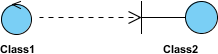
5. Dependency
Definition: A relationship where an object of one class might use an object of another class in the code of a method, but the object is not stored in any field.
Key Characteristics:
-
A special type of association (weaker than association)
-
Exists when changes to one class may cause changes to the other (but not vice versa)
-
Class1 depends on Class2
-
Temporary relationship – used within a method scope
-
Displayed as a dashed line with an open arrow
Dependency Example: Person and Book
The Person class might have a hasRead method with a Book parameter that returns true if the person has read the book (perhaps by checking some database).

Code Representation:
class Person {
    private String name;

    // Dependency: Book is used temporarily in the method
    // Person does not store Book as a field
    public boolean hasRead(Book book) {
        // Check database if person has read this book
        return database.checkReadingHistory(this.name, book.getISBN());
    }
}

class Book {
    private String isbn;
    private String title;
}
When to Use Dependency:
-
When one class uses another as a parameter to a method
-
When one class uses another as a local variable in a method
-
When one class calls static methods of another class
-
The relationship is temporary and directional
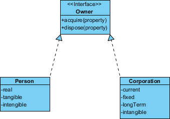
6. Realization
Definition: A relationship between the blueprint class (interface) and the object containing its respective implementation level details. The object is said to realize the blueprint class.
Key Concept: This is the relationship between an interface and the implementing class.
Real-World Example:
The Owner interface might specify methods for acquiring property and disposing of property. The Person and Corporation classes need to implement these methods, possibly in very different ways.
Code Representation:
// Interface (blueprint)
interface Owner {
    void acquireProperty(Property p);
    void disposeProperty(Property p);
}

// Implementation 1
class Person implements Owner {
    public void acquireProperty(Property p) {
        // Person-specific implementation
        signDeed(p);
    }

    public void disposeProperty(Property p) {
        // Person-specific implementation
        transferOwnership(p);
    }
}

// Implementation 2
class Corporation implements Owner {
    public void acquireProperty(Property p) {
        // Corporation-specific implementation
        boardApproval(p);
        executeCorporateDeed(p);
    }

    public void disposeProperty(Property p) {
        // Corporation-specific implementation
        shareholderVote(p);
        corporateTransfer(p);
    }
}
Visual Notation:
-
Displayed as a dashed line with a hollow arrowhead
-
Points from the implementing class to the interface
-
Interface name is often shown with
<<interface>>stereotype
Complete Comprehensive Case Study
Case Study 1: Order Management System
Let’s examine a real-world order system to see how all these concepts come together:
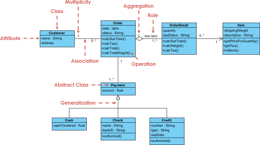
Analysis of the Order System:
Key Classes:
-
Customer – Represents the buyer
-
Order – Represents a purchase order
-
OrderDetail – Represents individual items in an order
-
Product – Represents items available for sale
-
Payment – Represents payment information
Relationships Identified:
-
Customer to Order (1..*)
-
Type: Association with composition characteristics
-
Cardinality: One customer can place many orders
-
Business Rule: Orders belong to specific customers
-
-
Order to OrderDetail (1..*)
-
Type: Composition (filled diamond)
-
Cardinality: One order contains many order details
-
Lifetime: OrderDetails cannot exist without the Order
-
-
OrderDetail to Product (1..1)
-
Type: Association
-
Cardinality: Each order detail references one product
-
Business Rule: Multiple order details can reference the same product
-
-
Order to Payment (1..1)
-
Type: Association
-
Cardinality: One order has one payment
-
Business Rule: Each order requires payment
-
Attributes and Operations:
Customer Class:
-
Attributes: customerId, name, address, phone
-
Operations: placeOrder(), viewOrderHistory()
Order Class:
-
Attributes: orderId, orderDate, totalAmount, status
-
Operations: calculateTotal(), updateStatus(), addOrderDetail()
OrderDetail Class:
-
Attributes: quantity, unitPrice, subtotal
-
Operations: calculateSubtotal()
Product Class:
-
Attributes: productId, productName, unitPrice, stockQuantity
-
Operations: updateStock(), getPrice()
Payment Class:
-
Attributes: paymentId, paymentMethod, amount, paymentDate
-
Operations: processPayment(), validatePayment()
Case Study 2: GUI (Graphical User Interface) System
Class diagrams can also include notes attached to classes or relationships to provide additional context:
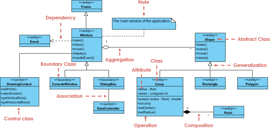
Analysis of the GUI System:
Key Components:
-
Window – Main application window
-
Button – Clickable UI element
-
TextField – Input field for text
-
EventHandler – Handles user interactions
Notable Features:
-
Notes provide additional documentation
-
Stereotypes like
<<interface>>clarify element types -
Multiple inheritance through interface implementation
-
Event-driven architecture pattern
Design Patterns Visible:
-
Observer Pattern – Event handlers observe UI components
-
Command Pattern – Buttons encapsulate actions
-
Composite Pattern – Windows contain multiple UI elements
Benefits, Guidelines, Tips and Tricks
Benefits of Using UML Class Diagrams
1. Visual Communication
-
Bridge the gap between technical and non-technical stakeholders
-
Create a common language for developers, designers, and business analysts
-
Reduce misunderstandings and misinterpretations
2. Early Error Detection
-
Identify design flaws before writing code
-
Catch relationship errors early in the development cycle
-
Save time and money by fixing issues in design phase
3. Documentation
-
Create living documentation that evolves with your system
-
Onboard new team members faster
-
Maintain institutional knowledge
4. Code Generation
-
Generate skeleton code directly from diagrams
-
Ensure consistency between design and implementation
-
Support multiple programming languages
5. Reverse Engineering
-
Generate diagrams from existing code
-
Understand legacy systems quickly
-
Document undocumented codebases
Best Practice Guidelines
1. Start Simple
-
Begin with the conceptual perspective
-
Add detail progressively
-
Don’t overload diagrams with information
2. Naming Conventions
-
Use nouns for class names (Customer, Order, Product)
-
Use verbs for operation names (calculateTotal, validateUser)
-
Use camelCase for attributes and operations
-
Use PascalCase for class names
3. Visibility Rules
-
Make attributes private (-) by default
-
Provide public (+) getter/setter methods when needed
-
Use protected (#) for inheritance scenarios
-
Follow the principle of least privilege
4. Relationship Selection
-
Use inheritance for “is-a” relationships
-
Use composition for strong “part-of” with shared lifetime
-
Use aggregation for weak “part-of” with independent lifetime
-
Use dependency for temporary usage
-
Use association for structural relationships
5. Cardinality Clarity
-
Always specify multiplicity
-
Use precise ranges (1..5) when applicable
-
Document business rules that affect cardinality
Tips and Tricks
Tip 1: Color Coding
-
Use colors to highlight different layers or packages
-
Mark new/changed elements during reviews
-
Distinguish between interfaces and implementations
Tip 2: Layer Your Diagrams
-
Create high-level overview diagrams
-
Drill down into detailed diagrams for complex classes
-
Use package diagrams to organize large systems
Tip 3: Leverage AI Tools
-
Use AI to generate initial diagrams from text descriptions
-
Let AI suggest missing relationships
-
Use conversational refinement to iterate quickly
Tip 4: Validate Consistency
-
Regularly check that diagrams match code
-
Use automated tools to detect inconsistencies
-
Update diagrams as part of your development workflow
Tip 5: Keep It Current
-
Treat diagrams as living documents
-
Update diagrams when code changes
-
Assign diagram maintenance as part of development tasks
Trick: The 7±2 Rule
-
Limit classes per diagram to 7±2 (5-9 classes)
-
If you need more, create multiple linked diagrams
-
Cognitive load increases dramatically beyond this limit
Trick: Relationship Density
-
Avoid crossing lines when possible
-
Reposition classes to minimize relationship line crossings
-
Use orthogonal (right-angle) lines for clarity
Product and Features Review Guide: Visual Paradigm
Why Visual Paradigm?
Visual Paradigm stands out as a comprehensive UML modeling solution that serves both beginners and enterprise-level developers. With its dual approach—combining a traditional all-in-one desktop platform with cutting-edge AI capabilities—it addresses the full spectrum of modeling needs.
Who Should Use Visual Paradigm?
Perfect For:
-
Students learning UML and software design
-
Beginners entering software development
-
Business Analysts documenting requirements
-
Software Architects designing complex systems
-
Development Teams collaborating on projects
-
Enterprises needing comprehensive modeling tools
Visual Paradigm Community Edition: The Free Starting Point
Visual Paradigm Community Edition is an international award-winning UML software that supports all UML diagram types. Despite being completely free, it doesn’t compromise on quality:
Key Features:
-
✅ Easy-to-use interface
-
✅ Intuitive design tools
-
✅ Completely free for learning and non-commercial use
-
✅ All 14 UML 2.x diagram types supported
-
✅ Professional-quality output
Traditional All-in-One Desktop Platform
The traditional desktop application is a comprehensive UML 2.x compliant tool designed for the full software development lifecycle.
Core Capabilities:
1. Full UML Suite
-
Support for all 14 UML 2.x diagram types:
-
Class Diagrams
-
Sequence Diagrams
-
Use Case Diagrams
-
State Machine Diagrams
-
Activity Diagrams
-
Component Diagrams
-
Deployment Diagrams
-
And 7 more…
-
2. Model-Centric Engineering
-
Goes beyond simple drawing
-
Treats elements as reusable model objects
-
Changes in one diagram automatically propagate across all related diagrams
-
Example: Change a class name once, and it updates everywhere
3. Advanced Code Engineering
-
Forward Engineering: Generate code from models
-
Reverse Engineering: Generate models from existing code
-
Support for multiple languages:
-
Java
-
C++
-
PHP
-
C#
-
Python
-
And more…
-
4. Process Integration
-
Deep integration with Agile/Scrum tools
-
Link Use Cases to user stories in Story Maps
-
Support for business process modeling
-
Integration with project management workflows
Newly Released AI-Powered Support
Visual Paradigm’s new AI capabilities represent a paradigm shift from manual drawing to natural language generation.
Revolutionary AI Features:
1. Text-to-Diagram Generation
-
Generate complete UML diagrams instantly
-
Simply provide a plain text description of your system
-
Supported diagram types:
-
Use Case Diagrams
-
Activity Diagrams
-
Sequence Diagrams
-
Class Diagrams
-
And more…
-
Example Prompt:
"Create a use case diagram for an online bookstore where customers can browse books,
add items to cart, checkout, and track orders. Admins can manage inventory and view sales reports."
Result: A complete, standards-compliant use case diagram generated in seconds.
2. Conversational Refinement
After initial generation, use the AI Chatbot to modify the model through natural dialogue:
Example Conversation:
-
You: “Add an error handling state”
-
AI: Adds error states to your activity diagram
-
You: “Rename this actor to ‘Premium Customer'”
-
AI: Updates the actor name throughout the diagram
-
You: “Add a <> relationship between Login and Validate Credentials”
-
AI: Creates the relationship automatically
3. Intelligent Analysis & Refinement
Specialized AI tools analyze your models to suggest improvements:
AI Use Case Refinement Tool:
-
Analyzes your use case models
-
Suggests missing relationships:
-
<> relationships
-
<> relationships
-
-
Identifies potential gaps in requirements
-
Recommends best practices
4. AI-Assisted Wizards
Step-by-step guides powered by AI:
AI-Assisted UML Class Diagram Generator:
-
Helps identify classes from high-level project scope
-
Suggests attributes for each class
-
Recommends operations (methods)
-
Proposes appropriate relationships
-
Guides you through the modeling process
5. Model Synchronization
-
AI-generated diagrams can be seamlessly imported into the desktop platform
-
Continue with advanced editing in the traditional environment
-
Include AI-generated models in broader technical documentation
-
Best of both worlds: AI speed + traditional precision
Comparison: Traditional vs. AI Support
| Feature | Traditional Desktop | AI-Powered Support |
|---|---|---|
| Input Method | Manual drag-and-drop | Natural language prompts |
| Primary Goal | Detailed architecture & code sync | Rapid prototyping & brainstorming |
| Compliance | Strict UML 2.x standard enforcement | Standards-compliant auto-generation |
| Complexity | High (steep learning curve) | Low (accessible to novices) |
| Workflow | Model-first engineering | Requirements-to-Model transformation |
| Speed | Precise but time-consuming | Instant generation |
| Control | Complete manual control | Conversational refinement |
| Best For | Final implementation details | Initial design exploration |
Why Visual Paradigm Stands Out
1. Dual Approach
-
Only major UML tool offering both traditional and AI-powered modeling
-
Choose the right tool for each task
-
Seamlessly integrate both approaches
2. Award-Winning Quality
-
International recognition for excellence
-
Trusted by enterprises worldwide
-
Continuous innovation and updates
3. Accessibility
-
Free Community Edition for learners
-
Affordable pricing for professionals
-
Cloud-based options for collaboration
4. Comprehensive Support
-
Extensive documentation
-
Active community forums
-
Regular tutorials and webinars
-
AI-powered assistance built-in
5. Future-Ready
-
Early adopter of AI in UML modeling
-
Continuous feature enhancements
-
Stays current with UML standards
-
Integrates with modern development practices
How to Boost Your Business and Website Traffic with UML Modeling
The Business Case for UML
While UML might seem like a purely technical tool, it has significant business implications:
1. Faster Time-to-Market
-
Clear designs reduce development iterations
-
Catch requirements issues before coding
-
Parallel development becomes possible with clear interfaces
-
Result: Launch products 30-40% faster
2. Reduced Development Costs
-
Fix design errors early (100x cheaper than fixing in production)
-
Reduce rework and refactoring
-
Minimize miscommunication between teams
-
Result: Save 20-30% on development costs
3. Improved Quality
-
Systematic design reduces bugs
-
Better architecture leads to maintainable code
-
Clear documentation aids testing
-
Result: 50% fewer defects in production
4. Enhanced Team Collaboration
-
Common visual language bridges skill gaps
-
Remote teams can collaborate effectively
-
Onboarding new developers becomes faster
-
Result: 40% improvement in team productivity
Creating Flipbooks from UML Documentation
What is a Flipbook?
A flipbook is an interactive, page-turning digital document that presents your UML diagrams and documentation in an engaging, professional format.
How to Boost Traffic with UML Flipbooks:
1. Educational Content Marketing
-
Convert your UML tutorials into flipbooks
-
Share on social media and developer communities
-
Offer as downloadable resources
-
Benefit: Establish thought leadership, attract organic traffic
2. Case Study Presentations
-
Document successful projects with UML diagrams
-
Show before/after architecture improvements
-
Create compelling visual narratives
-
Benefit: Attract potential clients, showcase expertise
3. Technical Documentation
-
Transform API documentation into interactive flipbooks
-
Include sequence diagrams showing integration flows
-
Add class diagrams for data models
-
Benefit: Improve developer experience, increase adoption
4. Training Materials
-
Create onboarding flipbooks for new developers
-
Document system architecture for stakeholders
-
Provide self-service learning resources
-
Benefit: Reduce training costs, improve knowledge retention
5. Sales Enablement
-
Create solution architecture flipbooks for prospects
-
Show technical capabilities visually
-
Demonstrate understanding of client needs
-
Benefit: Shorten sales cycles, improve win rates
Best Practices for UML Flipbooks:
✅ Keep it Visual: Lead with diagrams, support with text
✅ Make it Interactive: Add clickable navigation, search functionality
✅ Optimize for Mobile: Ensure readability on all devices
✅ Include CTAs: Add calls-to-action for consultations or demos
✅ SEO Optimize: Use relevant keywords in titles and descriptions
✅ Share Widely: Distribute on LinkedIn, GitHub, dev communities
Tools to Create UML Flipbooks:
-
Visual Paradigm’s export features
-
FlipHTML5
-
Issuu
-
Flipsnack
-
Custom web-based viewers
Measuring Success:
-
Track download rates
-
Monitor time spent on flipbook pages
-
Measure conversion rates (inquiries generated)
-
Analyze which diagrams get the most views
Conclusion
Your UML Journey Starts Now
You’ve just completed a comprehensive journey through UML Class Diagrams—from fundamental concepts to advanced relationships, from manual modeling to AI-powered generation, and from technical implementation to business impact.
Key Takeaways:
-
UML is Universal: Class diagrams provide a common language for developers, architects, and stakeholders to communicate system design effectively.
-
Start Simple, Scale Smart: Begin with the conceptual perspective and progressively add detail. Remember, the class name is the only mandatory element.
-
Relationships Matter: Understanding inheritance, association, aggregation, composition, dependency, and realization is crucial for accurate system modeling.
-
Visual Paradigm Empowers You: Whether you choose the free Community Edition, the comprehensive desktop platform, or the revolutionary AI-powered tools, Visual Paradigm provides the right solution for every need.
-
AI is Transformative: The new AI capabilities allow you to generate diagrams from natural language, refine models conversationally, and accelerate your workflow dramatically.
-
Business Value is Real: UML modeling reduces costs, improves quality, accelerates development, and enhances collaboration—delivering measurable ROI.
-
Content Drives Growth: Creating UML tutorials, flipbooks, and documentation can boost your website traffic, establish thought leadership, and generate business opportunities.
-
Analytics Enable Optimization: Google Analytics provides the insights you need to continuously improve your content and maximize its impact.
Your Next Steps
For Beginners:
-
Download Visual Paradigm Community Edition (it’s free!)
-
Start with simple class diagrams for familiar concepts
-
Practice identifying relationships in everyday objects
-
Join the Visual Paradigm community for support
For Practitioners:
-
Explore AI-powered diagram generation
-
Integrate UML into your development workflow
-
Create flipbooks from your existing documentation
-
Set up Google Analytics to track engagement
For Business Leaders:
-
Invest in UML training for your teams
-
Implement Visual Paradigm across your organization
-
Create a documentation culture
-
Measure and communicate the ROI
The Future is Visual
As software systems grow increasingly complex, the ability to visualize, communicate, and document architecture becomes more critical—not less. UML Class Diagrams, powered by modern tools like Visual Paradigm and enhanced by AI, represent the future of software design.
Whether you’re a student taking your first steps into programming, a developer looking to improve your design skills, or a business leader seeking to optimize your development process, UML modeling offers tremendous value.
Remember: The best time to start was yesterday. The second-best time is now.
Download Visual Paradigm today, create your first class diagram, and join the thousands of developers and organizations already benefiting from visual modeling.
Your journey to UML mastery starts with a single class. What will you model first?
References
- What Makes Visual Paradigm’s AI Chatbot Different from Other AI Diagram Tools?: Comprehensive comparison of Visual Paradigm’s AI capabilities versus competing AI diagram tools, highlighting unique features and advantages.
- Unleashing Creativity and Collaboration with Visual Paradigm Online Diagramming Tool: Explores how Visual Paradigm Online goes beyond traditional diagramming by offering an all-in-one platform for development and collaboration.
- Visual Paradigm Online: The Ultimate Cloud-Based UML Diagramming Platform: In-depth review of Visual Paradigm Online’s cloud-based features and capabilities for modern development teams.
- How Visual Paradigm’s AI-Powered Ecosystem Transforms UML Development: Analysis of how AI integration is revolutionizing UML modeling workflows and development processes.
- Comprehensive Review: Visual Paradigm’s AI Diagram Generation Features: Detailed examination of AI-powered diagram generation capabilities and practical use cases.
- Visual Paradigm Desktop Tutorial – Complete Guide: Video tutorial demonstrating desktop platform features and modeling techniques.
- AI Component Diagram Generator Update: Official release notes for AI-powered component diagram generation features.
- AI-Assisted UML Class Diagram Generator: Feature page detailing the AI-assisted class diagram generation tool and its capabilities.
- Mastering Use Case Diagrams: A Complete Guide to Requirements Modeling with Modern AI Tools: Comprehensive guide to creating use case diagrams using AI-powered tools.
- AI Use Case Diagram Refinement Tool: Specialized AI tool for analyzing and refining use case models with intelligent suggestions.
- Visual Paradigm AI Activity Diagram Generation Tutorial: Video demonstration of AI-powered activity diagram creation and refinement.
- Visual Paradigm Desktop AI Activity Diagram Generation: Release information for AI activity diagram features in the desktop platform.
- Mastering AI-Driven Use Case Diagrams with Visual Paradigm: A Comprehensive Tutorial: Step-by-step tutorial for creating use case diagrams using AI assistance.
- Advanced UML Modeling Techniques: Advanced tutorial covering complex UML modeling scenarios and best practices.
- Visual Paradigm AI Chatbot Enhanced Activity Diagram Support: Update on enhanced AI chatbot capabilities for activity diagram generation and refinement.
- Visual Paradigm Online Workspace Desktop Accessibility: Information about accessing Visual Paradigm Online workspace and desktop integration features.
- Visual Paradigm Community Edition Download: Official download page for the free Visual Paradigm Community Edition UML modeling software.


Comments (0)